Frame
Materials
Bare-frame quantities. Custom top panels and the belly pan are not yet received.
| Material | Needed |
|---|---|
| Cut aluminum rails | 17 |
| Assembled MK5n modules, with their supplied chassis-mounting hardware | 4 |
| AndyMark am-4762 tube plugs | 22 |
| WCP-1060 corner gussets | 20 individual plates |
| WCP-1070 T-gussets | 8 individual plates |
| REV seven-position nut strips | 8 |
| REV nine-position nut strips | 2 |
| WCP-0336 nut strips | 2 for the base; keep the other 2 for the lift |
| McMaster 92510A647 aluminum sleeves, 3/4 inch long | 56 |
| #10-32 × 3/8-inch button-head screws | 94 |
| #10-32 × 1/2-inch button-head screws | 28 |
| #10-32 × 5/8-inch button-head screws | 100 for the frame; reserve 22 more for the belly pan |
| #10-32 × 1-3/4-inch button-head screws | 56 |
| AndyMark am-1042 #10-32 nylock nuts | 100 for the frame; reserve 30 more for panels |
| Zernmiarder M5 flat washers, BOM B0DK6K87Z7 | 284 for the frame; reserve 56 more for panels without lift |
| #10-32 × 1-inch button-head screws | Reserve 26 for panels without lift |
Lower ring assembly
Four 16-inch rails and four assembled MK5n modules form the lower outer ring. The two 22.5-inch internal crossmembers are a separate operation. No custom plates are needed for this loose assembly.
Based on the SDS MK5n Assembly Guide, v20260103 : layouts on page 4, chassis mounting in Step 28 on page 32, tube dimensions on page 34.
Clearance requirement: SDS specifies a 3/16-inch corner chamfer to clear the wheel. Square-ended rails seating against a module does not establish full steering clearance. The steps below are a reversible, unpowered fit-up; omission of that chamfer is not approved by this guide.
1. Prepare the four rails
| Parts for this step | Quantity |
|---|---|
16-inch / 40.64 cm rails: mx0, mx1, my0, my1 | 1 each |
| REV-29-2945 #10-32 × 5/8-inch button-head screws | 8 |
| Zernmiarder M5 flat washers | 8 |
| AndyMark am-1042 #10-32 nylock nuts | 8 |
Tools: tape measure, IRWIN square, Bondhus 1/8-inch hex key, TEKTON 3/8-inch wrench; BOM hook/pick set for positioning screws.
- Check that each rail is 16 inches long and its cut edges are free of burrs. Keep the member labels visible.
- Orient each rail 2 inches tall and 1 inch wide. Identify the narrow face that will point down.
- Find the two existing bottom-face holes 7¼ inches and 8¾ inches from either end. These are the future belly-pan mounts; do not drill new holes.
- Feed two 5/8-inch screws through an open tube end. Seat their heads inside the bottom wall, with the threaded ends pointing down. Reach each head through the opposite top-wall hole with the straight end of the 1/8-inch key.
- Temporarily retain each screw with one washer and one nut underneath the tube. Leave them loose; these washers and nuts will be removed and reused below the belly pan when it arrives.
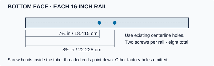
These eight sets come from the 22 reserved belly-pan sets, not the frame-gusset allocation. The other 14 will go in the internal crossmembers.
Preloading is an access convenience, not a reason by itself to dismantle an assembled ring. Later installation is possible if access remains to place the screw heads inside the tubes; the top factory holes provide hex-key access, not clearance for the screw heads.
2. Join mx0 and my0 at the first corner
| Parts for this step | Quantity |
|---|---|
Prepared rails mx0 and my0 | 1 each |
| Assembled MK5n, layout B | 1 |
| SDS-supplied #10-32 × 2½-inch socket-head mounting screws | 4 |
Tool: Bondhus 5/32-inch hex key.
- On a stable surface, arrange
mx0on the right andmy0along the bottom of the drawing. Place the B module at their lower-right corner, with its main plate above the rails and wheel below. Keep the system unpowered. - Slide each rail end between the module’s upper main plate and lower plate. Match the housing orientation in the drawing; use the B marking on the module to identify its layout.
- Align the two mounting holes at each rail end: ¼ inch and 1¾ inches from the end (0.635 cm and 4.445 cm). These are the first and fourth holes on the half-inch factory grid.
- Insert two screws upward through each rail end: screw head below the module’s lower plate, shaft through both tube walls, threads into the upper main plate. Start all four by hand, then turn only enough to retain the parts. Leave the joint loose.
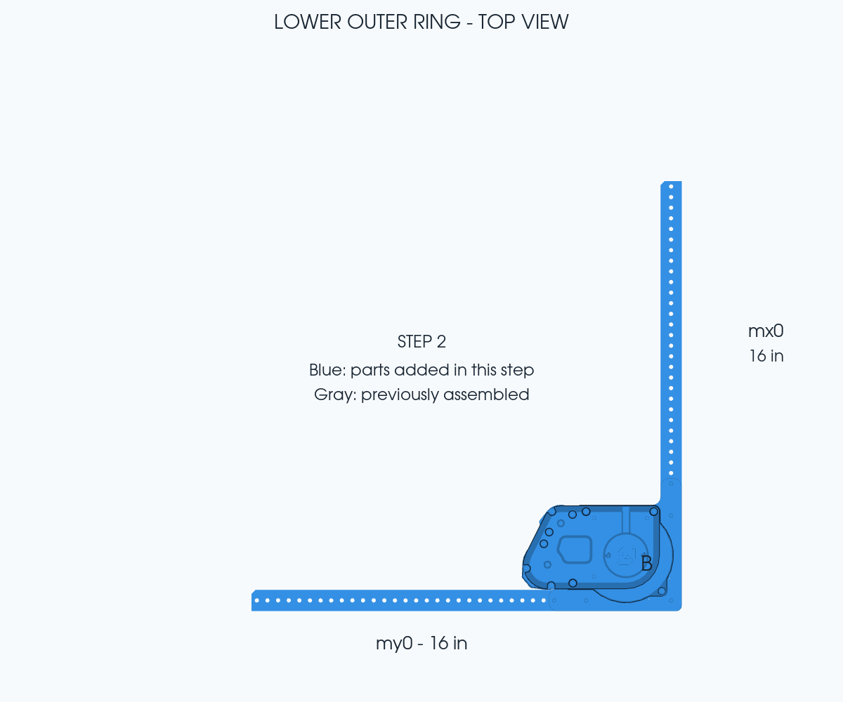
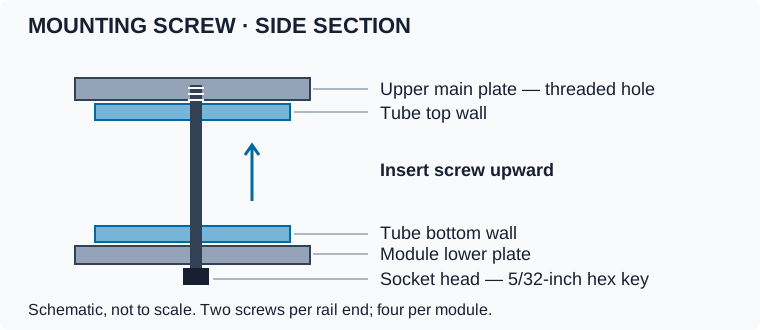
Use the supplied 2½-inch socket-head screws, not the 1¾-inch frame button-head screws. This SDS joint does not use the separate frame washers, nylock nuts or anti-crush sleeves. Do not use a screw to force a misaligned rail into place. Threadlocker and final tightening are deferred until the remaining frame fit and clearance are resolved.
3. Add my1 and the second module
| Parts for this step | Quantity |
|---|---|
Prepared rail my1 | 1 |
| Assembled MK5n, layout A | 1 |
| SDS #10-32 × 2½-inch socket-head mounting screws | 4 |
Tool: Bondhus 5/32-inch hex key.
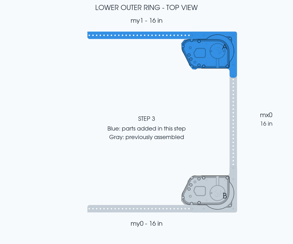
- Place the A module at the upper-right corner, at the free end of
mx0. - Fit
my1into its other mounting side, extending left across the top of the drawing. - Start two screws upward through
mx0and two upward throughmy1, exactly as in Step 2. Leave all four loose.
4. Add mx1 and the third module
| Parts for this step | Quantity |
|---|---|
Prepared rail mx1 | 1 |
| Assembled MK5n, layout B | 1 |
| SDS #10-32 × 2½-inch socket-head mounting screws | 4 |
Tool: Bondhus 5/32-inch hex key.
- Place the B module at the upper-left corner, at the free end of
my1. - Fit
mx1into its other mounting side, extending down the left side of the drawing. - Start two screws upward through
my1and two upward throughmx1. Leave all four loose.
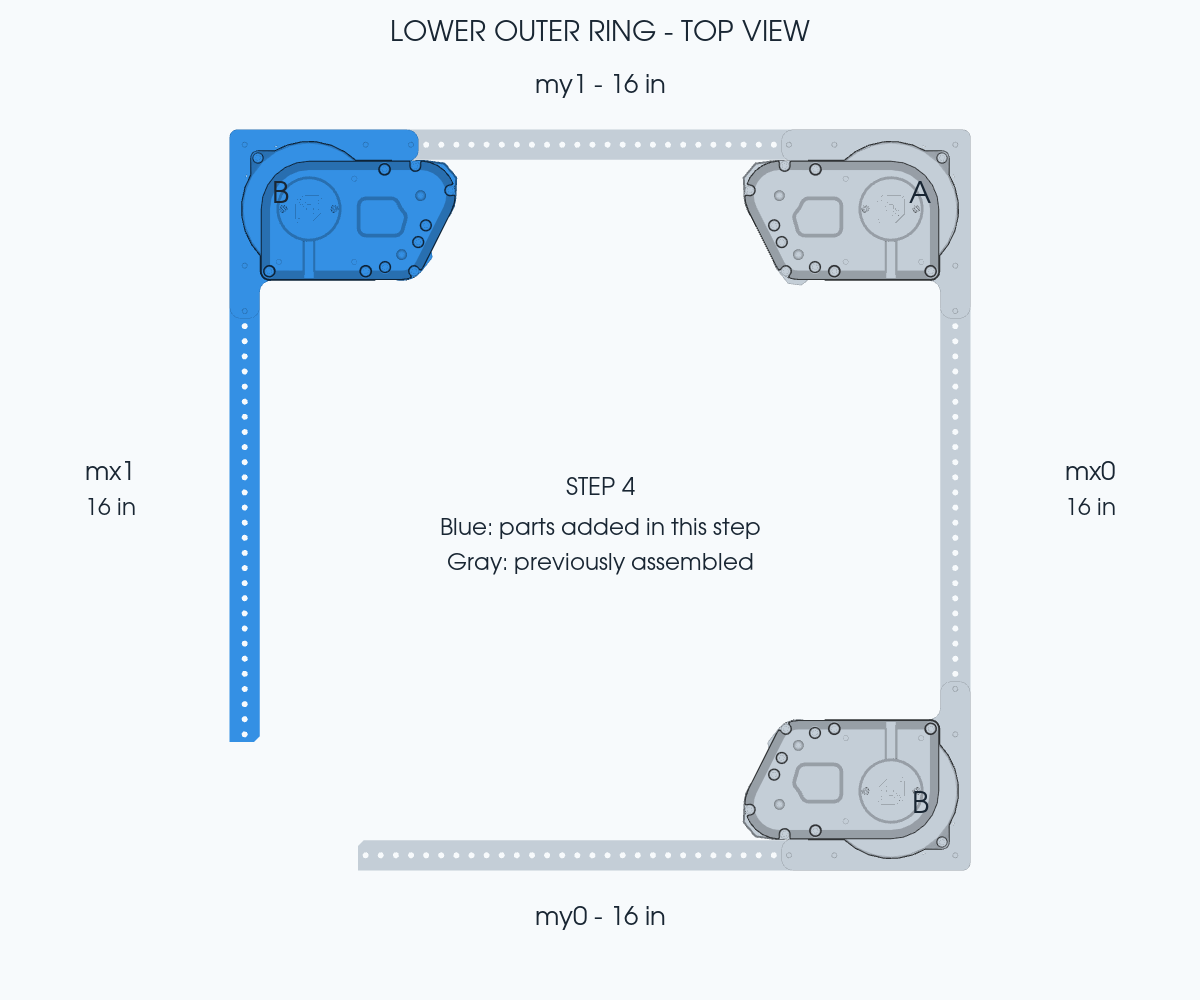
5. Close the last corner
| Parts for this step | Quantity |
|---|---|
| Assembled MK5n, layout A | 1 |
| SDS #10-32 × 2½-inch socket-head mounting screws | 4 |
Tool: Bondhus 5/32-inch hex key.
- Place the last A module at the lower-left corner, between the free ends of
mx1andmy0. - Bring both rail ends into its mounting channels. If they do not line up freely, adjust the loose joints; do not pull them together with the screws.
- Start two screws upward through each rail end. There should now be 16 SDS mounting screws: four per module.
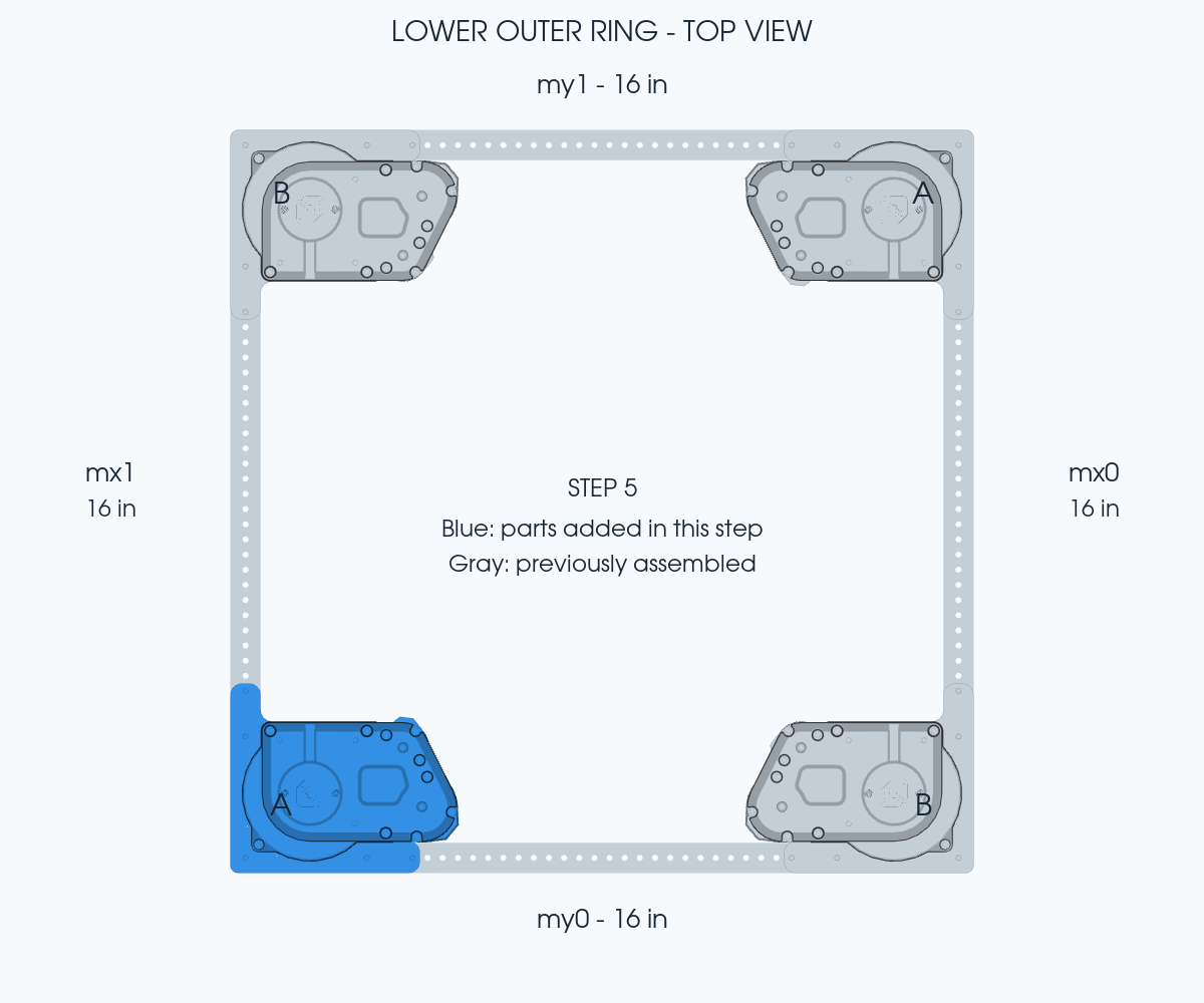
6. Check the loose ring
Parts: the assembled outer ring; no additional hardware.
Tools: IRWIN square and tape measure.
- Check that every rail sits flat between its module plates. Check the four rail-to-rail angles with the square.
- Measure both diagonals between corresponding outer-corner points. Adjust the loose ring until the diagonals agree and the corners remain square. No manufacturing tolerance is specified here.
- Check that matching module layouts occupy opposite corners. This drawing is rotated relative to the SDS page-4 example; identify A/B from the actual part markings.
- With power disconnected and each wheel clear of the supporting surface, gently check the module’s full 360° steering travel, not just wheel rolling. Stop at any contact; do not force it. Inspect both rail ends at each module. Static seating alone does not resolve the SDS wheel-clearance requirement.
- Leave the ring loose and unpowered. Concealed crossmember/post hardware and the supplier’s tube-end clearance requirement must be resolved before final tightening. SDS calls for Loctite 243 at final screw installation but gives no chassis-mount torque in Step 28; do not borrow the wheel-subassembly torque.
At this stage: four rails, four modules, 16 loosely installed mounting screws and eight retained belly-pan screws. No gussets, tube plugs, sleeves, crossmembers or custom panels have been installed.
Inner rail materials — xm0 and xm1
Quantities below cover both lower inner rails and all four end joints. All hardware comes from the existing BOM; these are individual pieces, not packs. Each rail uses half of every hardware quantity listed.
| Material | Total for both rails | Purpose |
|---|---|---|
Rails xm0 and xm1, 22½ in / 57.15 cm long | 1 each | Lower inner rails |
| AndyMark am-4762 tube plugs | 4 | One in each rail end |
| WCP-1070 T-gussets | 4 plates | One over each end joint |
| REV seven-position nut strips, REV-21-3424 | 4 strips | Back the T-gusset crossbars inside my0 and my1 |
| #10-32 × 3/8-inch button-head screws, REV-29-2941 | 20 | Tube-plug attachments; no washers |
| #10-32 × 1/2-inch button-head screws, REV-29-2943 | 4 | One gusset-to-plug screw per joint |
| #10-32 × 5/8-inch button-head screws, REV-29-2945 | 36 | 28 into nut strips; 8 into loose nuts |
| Zernmiarder M5 flat washers, BOM B0DK6K87Z7 | 48 | 40 under gusset screw heads; 8 beside the internal loose nuts |
| AndyMark am-1042 #10-32 nylock nuts | 8 | Two inside each inner-rail end, behind the gusset |
Not used for these joints: WCP-1060 corner gussets, nine-position strips, WCP-0336 strips, 1¾-inch through-bolts or aluminum sleeves.
Belly pan, separate allocation: reserve another 14 × 5/8-inch screws, 14 M5 washers and 14 am-1042 nuts for the pan mounts on these two rails—seven sets per rail. They are not included in the joint quantities above and are not needed just to attach the rails and gussets. The eight outer-ring pan sets remain a separate allocation too.
BOM tools: Bondhus 1/8-inch hex key, TEKTON 3/8-inch wrench, hook/pick set, IRWIN square and tape measure.
Inner rails — first T-gusset
Preassemble one T-gusset on one end of xm0, off the frame. The tube end must remain open for access to the two internal nuts.
| Parts for this step | Quantity |
|---|---|
Rail xm0, 22½ inches long | 1 |
| WCP-1070 T-gusset | 1 plate |
| #10-32 × 5/8-inch button-head screws | 2 |
| M5 flat washers | 4 |
| am-1042 #10-32 nylock nuts | 2 |
Tools: Bondhus 1/8-inch hex key, TEKTON 3/8-inch wrench; hook/pick set for positioning the internal hardware.
- Orient
xm02 inches tall, 1 inch wide. Lay the gusset flat on its narrow top face, with the T’s stem pointing along the rail and its wide crossbar extending beyond the open end. - Align the stem’s three centerline mounting holes with the rail. Leave the hole ½ inch / 1.27 cm from the end empty; it will attach to the tube plug later. Use the next two holes, 1 inch / 2.54 cm and 1½ inches / 3.81 cm from the end, highlighted below. The hole directly over the cut edge also stays unused.
- Put one washer on each 5/8-inch screw and insert the screws downward through the gusset and rail’s top wall.
- Through the open tube end, place one washer and one locknut on each screw. The nut’s nylon collar faces away from the tube wall. Hold the nut with the 3/8-inch wrench and turn the screw with the 1/8-inch key. If the wrench cannot reach and engage the nut, leave the end open; do not insert the plug.
- Retain both nuts but leave the gusset slightly adjustable for the frame fit-up. No threadlocker or final tightening at this stage.
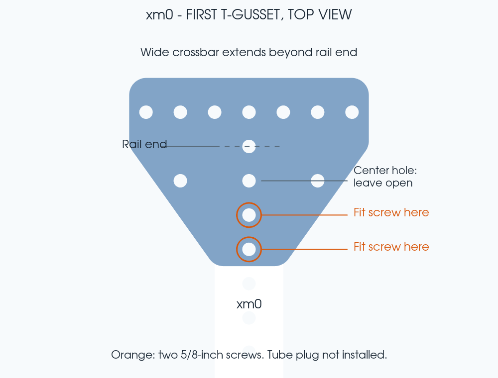
Each screw’s stack: screw head → washer → gusset → tube top wall → washer → nut inside the tube.
End state: one gusset retained by two screws, four washers and two internal nuts. All other gusset holes remain empty; the tube plug and nut strip are not installed.
Inner rails — remaining three gussets
Repeat the same attachment on the other end of xm0 and both ends of xm1.
| Additional parts for this step | Quantity |
|---|---|
Rail xm1, 22½ inches long | 1 |
| WCP-1070 T-gussets | 3 plates |
| #10-32 × 5/8-inch button-head screws | 6 |
| M5 flat washers | 12 |
| am-1042 #10-32 nylock nuts | 6 |
Tools: Bondhus 1/8-inch hex key and TEKTON 3/8-inch wrench; hook/pick set as needed.
- Fit the second gusset to the other end of
xm0. Both gussets belong on the same narrow top face. Rotate the second gusset 180° in that plane: its wide crossbar extends beyond its rail end, and its stem points toward the rail’s center. - At that end, use the holes 1 inch / 2.54 cm and 1½ inches / 3.81 cm from the cut end. Each screw has one washer under its head and one washer beside the nut inside the tube. Leave the nearer ½-inch hole and all crossbar holes empty.
- Repeat at both ends of
xm1, with both gussets on its narrow top face and their crossbars extending beyond opposite ends. - Keep all four gussets slightly adjustable. Leave all four tube plugs out; the internal nuts must remain accessible. No threadlocker or final tightening yet.
End state: two rails, each with a gusset at both ends. Installed totals are 4 gussets, 8 five-eighth-inch screws, 16 washers and 8 locknuts. Neither rail is attached to the outer ring yet.
Where the tube plugs go
The four am-4762 plugs go inside the four open ends of xm0 and xm1, underneath the gussets: one at each end of each rail. They do not sit between the rails or inside my0/my1 for these joints.
Each plug’s end face sits flush with the inner rail’s cut end. Its body occupies the first ¾ inch / 1.905 cm inside the tube. Screws through the adjoining outer rail (my0 or my1) thread into that end face to connect the rails. The gusset hole left empty ½ inch from the end is directly above a threaded hole in the plug.
The two gusset nuts already being fitted sit farther into the rail, at 1 inch and 1½ inches from the end. That is why the plugs stay out during this step: they would restrict access to those nuts.
Inner rails — first tube plug
Work on one end of xm0, out of the frame. Complete the dry fit and secure the two internal gusset nuts at this end before inserting the plug; the plug restricts wrench access.
| Parts for one end | Quantity |
|---|---|
| AndyMark am-4762 tube plug | 1 |
| #10-32 × 3/8-inch button-head screws, REV-29-2941 | 2, no washers |
| #10-32 × 1/2-inch button-head screw, REV-29-2943 | 1 |
| Zernmiarder M5 flat washer | 1, under the 1/2-inch screw head |
Tool: Bondhus 1/8-inch hex key.
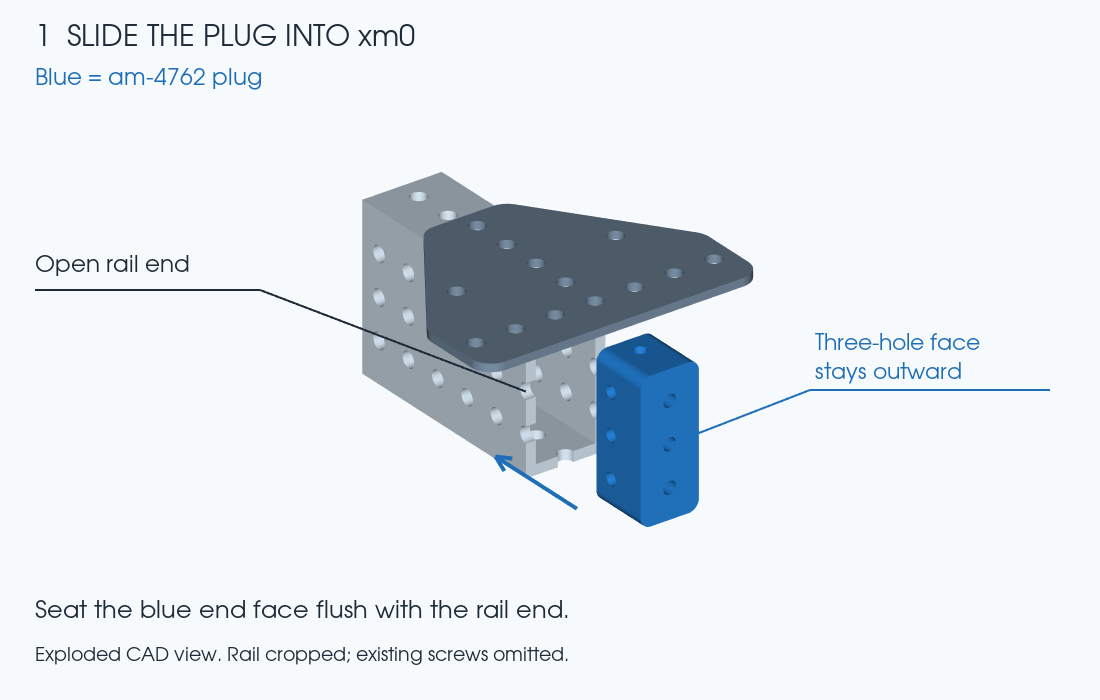
- Slide the plug into the open rail end with its three-hole end face pointing outward. Seat that face flush with the cut end. Do not hammer it or use screws to pull it past an obstruction.
- Align the plug’s threaded holes with the rail holes ½ inch / 1.27 cm from the cut end.
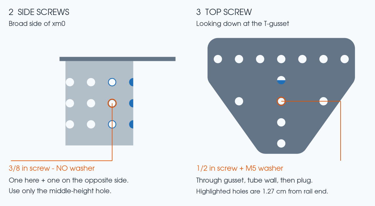
- On each of the rail’s two broad sides, insert one 3/8-inch screw through the middle-height hole into the plug. Use two screws total, directly opposite each other, with no washers. Leave the upper and lower side holes empty.
- Put the M5 washer on the 1/2-inch screw. Insert it downward through the empty gusset hole ½ inch / 1.27 cm from the rail end, through the tube’s top wall and into the plug.
- Start all three screws a few turns before snugging them gently. If a screw will not start freely, realign the plug rather than forcing the threads. No threadlocker or final tightening at this stage.
End state: one plug seated flush and retained by three screws. Its three outward-facing threaded holes remain empty for the later connection to my0 or my1. The inner rail is not yet attached to the outer ring.
First upright: lower gussets
Prepare the bottom of pxpy, off the frame. Use its factory end as the bottom: the first hole center is 1.27 cm from that end. The full post is 26.67 cm long.
| Parts for this step | Quantity |
|---|---|
| WCP-1060 L-shaped gussets | 2 |
| #10-32 × 1¾-inch button-head screws | 2 |
| McMaster 92510A647 aluminum sleeves, ¾ inch long | 2 |
| Zernmiarder M5 flat washers | 4 |
| AndyMark am-1042 #10-32 nylock nuts | 2 |
Tools: Bondhus 1/8-inch hex key and TEKTON 3/8-inch wrench.
Position the gussets
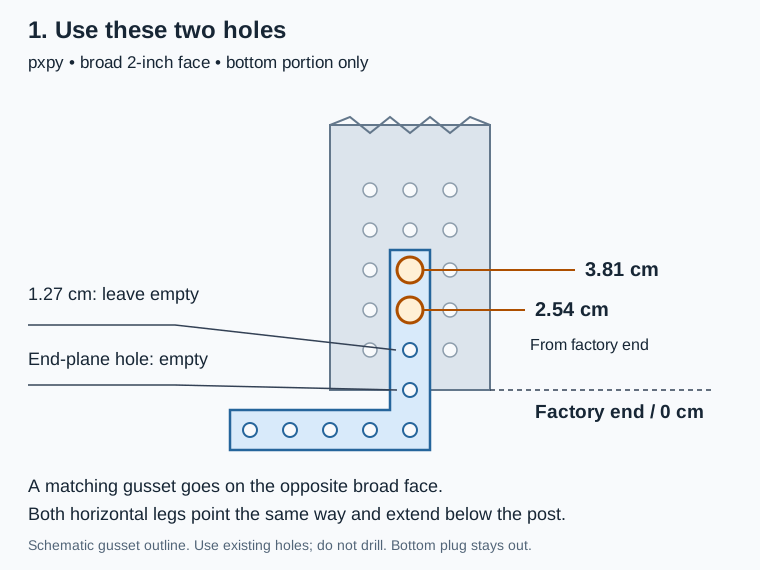
Place one gusset on each broad, 2-inch face. Their horizontal legs point the same way. Use the center-column holes 2.54 cm and 3.81 cm above the factory end. The horizontal legs extend below the post to overlap the base rail later.
Install the two through-bolts
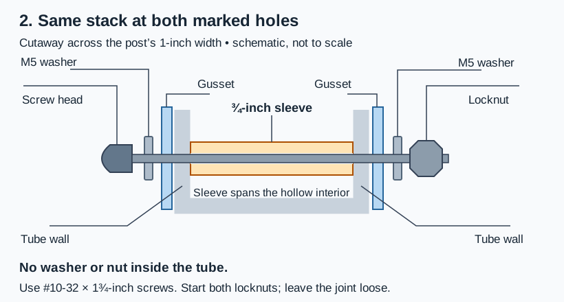
- Put one washer on a long screw and pass it through the first gusset and tube wall.
- Feed a sleeve through the open bottom of the post and align it with that screw. Pass the screw through the sleeve, opposite tube wall and second gusset.
- Add a washer and nylock nut outside the second gusset. Start the nut without tightening the joint.
- Repeat at the other marked hole. Keep the bottom plug out and the 1.27 cm holes empty.
First upright: bottom plug
Keep the two lower gussets and their long through-bolts on pxpy. Fit one am-4762 plug using two #10-32 × ½-inch screws and two M5 washers. Use the 1/8-inch hex key.
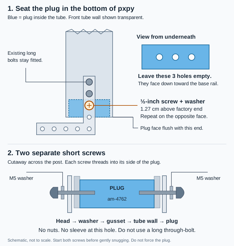
- Slide the plug into the factory/bottom end. Its three-hole end face points out and sits flush with the tube end. Do not force it past an obstruction.
- Align the plug’s threaded side holes with the empty gusset holes 1.27 cm from the bottom.
- Install one ½-inch screw with an M5 washer on each side, through gusset and tube wall into the plug. There are no separate nuts or sleeve at this hole.
- Start both screws before gently snugging. Leave the three exposed bottom-face holes empty for attachment to the base rail.
Attach the first upright to the base rail
Hold the prepared upright in its dry-fit position. Use three #10-32 × ⅜-inch screws without washers and the straight end of the 1/8-inch hex key. Leave the gussets’ horizontal bolt holes empty until these three screws are fitted.
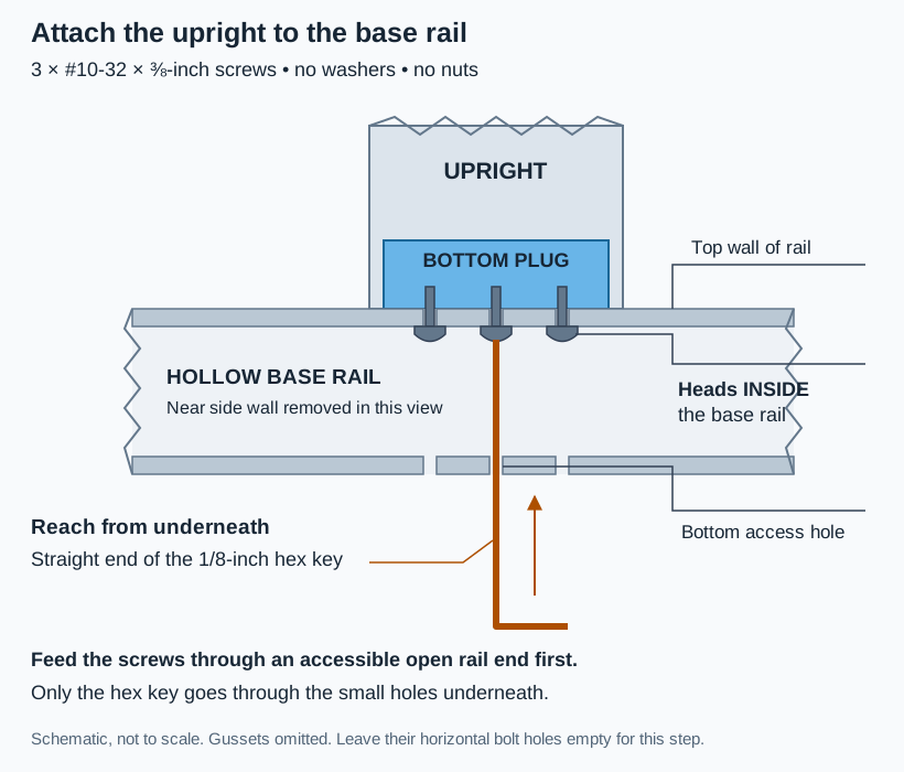
- Feed each screw through an accessible open end of the base rail. The small holes underneath are for the hex key, not for passing the screw heads through.
- Position each screw head inside the base rail, with the shaft pointing upward through the top wall into the plug.
- Insert the straight hex key from underneath through the aligned bottom-wall hole to reach the screw head. Hold the upright and start all three screws before gently snugging them.
If the open rail end cannot be reached, leave this joint unfastened until screw-loading access is established. Do not substitute a long screw through both walls.
Upper upright gussets
The upper gussets point away from the other upright on the same base rail, opposite the lower gussets. Put one on each broad face; both plates on a post point the same way. Leave the 24½-inch upper rails off during this step.
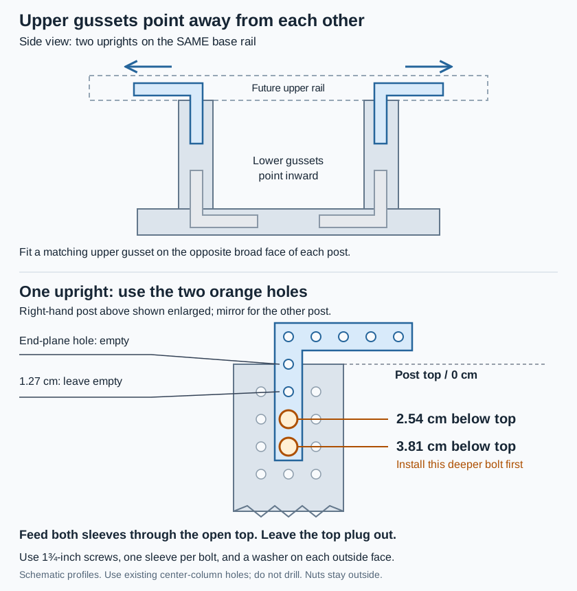
For one upright: two WCP-1060 gussets, two #10-32 × 1¾-inch screws, two ¾-inch aluminum sleeves, four M5 washers and two #10-32 nylock nuts. Use the Bondhus 1/8-inch hex key and TEKTON 3/8-inch wrench.
- Align the gussets with the center-column holes 2.54 cm and 3.81 cm below the post top. Their horizontal legs extend above the post.
- Feed the deeper sleeve through the open top and install its bolt at 3.81 cm. Repeat at 2.54 cm.
- Each bolt stack is head → washer → gusset → tube wall → sleeve → opposite wall → gusset → washer → nut. Leave the joint adjustable.
Keep the top plug out, and leave the 1.27 cm and end-plane gusset holes empty for this step.
Upright top plugs
Install each top plug after the upright’s two upper gusset through-bolts and sleeves are fitted. Keep the long upper rails off.
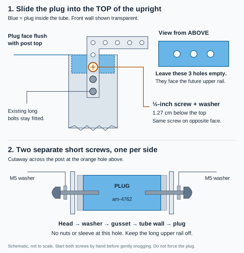
For each upright: one am-4762 plug, two #10-32 × ½-inch screws and two M5 washers. All four uprights use four plugs, eight screws and eight washers. Use the Bondhus 1/8-inch hex key.
- Slide the plug into the top of the upright. Its three-hole end face points upward and sits flush with the tube end.
- Align its threaded side holes with the gusset holes 1.27 cm below the top.
- Install one short screw from each side: head → washer → gusset → tube wall → plug. These are two separate screws, with no nuts or sleeve at this hole.
- Start both screws by hand before gently snugging them. Leave the three upward-facing threaded holes empty for the upper rail attachment.
Preload the upper outer nut strips
Work on one loose 24½-inch / 62.23 cm upper outer rail at a time. Each rail needs one REV nine-position #10-32 nut strip and one #10-32 × ⅜-inch screw for temporary retention. Use the Bondhus 1/8-inch hex key. These strips support the top panels.
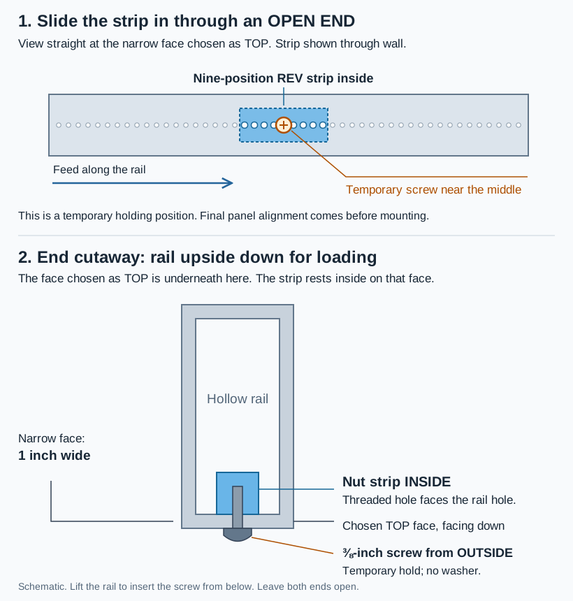
- Choose a narrow 1-inch face as the top. Lay that face downward so the strip can rest against its inside surface.
- Slide the strip lengthwise through an open rail end, with its threaded holes facing the holes in that narrow face. Move it near the middle.
- Lift the rail enough to insert a ⅜-inch screw from outside that face through an aligned rail hole into the strip. Start it by hand and gently snug it to hold the strip. This temporary screw uses no washer.
This position is temporary, not the final panel-hole alignment. Keep both ends open and leave the rail off the uprights until the internal hardware and exact strip position are set. Remove the temporary screw when replacing it with the panel attachment hardware.
Inner-rail screws in ty0 and ty1
Each cross rail needs six #10-32 × ⅜-inch screws, without washers or nuts, to attach the two inner rails through their end plugs. Keep ty0/ty1’s own end plugs out while loading these screw heads.
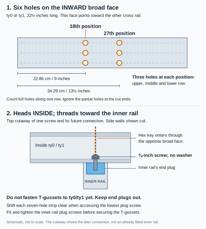
- Use the inward-facing broad, 2-inch face, toward which the long legs of the end L-gussets point.
- Count along one row from a cut end, excluding the partial end hole. At positions 18 and 27, use all three vertically stacked holes. These positions are 22.86 cm and 34.29 cm from that end.
- Load screw heads through the open ends. Each head remains inside the cross rail; its threads project through the inward-facing wall toward an inner rail.
T-gusset order
Leave the T-gusset crossbars unattached to ty0/ty1 until the three plug screws at each inner-rail end are fitted and tightened. A straight 1/8-inch hex key reaches those heads through the opposite broad face. The T-gusset stems can be prepared on the loose inner rails before fitting their end plugs; the crossbars must remain unfastened during driver access.
The saved geometry places the top of each seven-position strip at the same height as the lowest plug-screw axis. That strip therefore occupies part of the straight driver’s path. Remove its temporary retaining screw and slide the strip along the rail clear of that column while accessing the lowest screw. Keep the strip inside the rail. Once the plug screws are tightened and the driver is removed, return the strip to its marked position before installing the T-gusset. Do not force the driver past a strip.
Upper inner rail: first T-gusset
Prepare one end of one upper inner rail, off the frame. Fit one WCP-1070 T-gusset on the bottom narrow, 1-inch face, not a pair of plates.
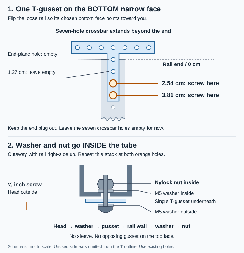
For this end: one T-gusset, two #10-32 × ⅝-inch screws, four M5 washers and two #10-32 nylock nuts. Use the Bondhus 1/8-inch hex key and TEKTON 3/8-inch wrench.
- Place the gusset on the chosen bottom face. Its wide seven-hole crossbar extends beyond the tube end; its stem runs along the rail.
- Attach the stem through the second and third full rail holes, 2.54 cm and 3.81 cm from the end. Do not count the partial hole at the cut edge.
- Each stack is head → washer → gusset → rail wall → washer → nut inside the tube. Fit the internal washers and nuts through the open end. Start both screws before snugging; keep the joint adjustable for fit-up.
Leave the first full hole at 1.27 cm empty for the plug-backed screw. Keep the end plug out until the internal nuts and other required internal hardware are fitted. The crossbar remains unattached to ty0/ty1 during this step.