Lift
Materials
Quantities below are for one lift. Use the with-lift BOM for the allocated fasteners; shared base parts are reused.
| Part | Quantity | Notes |
|---|---|---|
| MISUMI HFS8-80160-1170-TPW mast | 1 | Guide-seat machining required. |
| Steel cradle | 1 | Custom fabrication. |
| HIWIN HGR20 rails, 1120 mm | 2 | Keep guide blocks on rails or transfer retainers. |
| HIWIN HGH20CA blocks | 4 | Two per rail. |
| Carriage | 1 | Current guide seats and cam holes; custom fabrication. |
| MISUMI BSSRK2020-1100-F36-P12 screw and ballnut | 1 set | Keep ballnut on screw. |
| BNFA2020R-25 ballnut bracket | 1 | Use allocated flange hardware. |
| Fixed/floating supports and bearing adapters | 1 set | Custom adapters need final drawings. |
| Kraken X60 | 1 | Fifth purchased motor; four belong to the base. |
| REV MAXPlanetary base, brake, 3:1 cartridge, input coupler | 1 each | SplineXS input. |
| Machined output shaft | 1 | Custom fabrication. |
| Ruland MJC33-12-A hubs | 2 | One at each shaft. |
| Ruland JD21/33-98R spider | 1 | Between the two hubs. |
| HFS8-4080-710 arm beam and HBLUQ8 support | 1 each | Silver/clear anodized. |
| YAM Ultra arms | 2 | Add after checking unloaded lift travel. |
| Limit switches, mast brackets and moving cam | 2 switches, 2 brackets, 1 cam | Use the BOM hardware allocation. |
| D435i, printed mast bracket and end cap | 1 each | Camera hardware below. |
| End-stop hardware | See BOM | Mounting arrangement remains under review. |
Tools
| Tool | Notes |
|---|---|
| Metric and imperial hex tools | Reuse the existing sets. |
| Specified torque tools | Use each joint’s source specification. |
| Square and measuring tools | Reuse the frame tools. |
| Independent carriage support | Required during assembly; the ball screw can backdrive. |
Manufacturer instructions
- HIWIN linear guideway assembly manual : rail installation and alignment.
- REV MAXPlanetary assembly for Kraken and other 500-size motors : input stage and cartridge assembly. Use our allocated #10-32 × 3/8 in motor screws; the generic example lists 1/2 in screws.
- REV brake cartridge guidance : brake placement and assembly tips.
- REV output-shaft retention : install the retention screw before closing the gearbox. Our machined shaft must follow its final drawing.
Lift layout
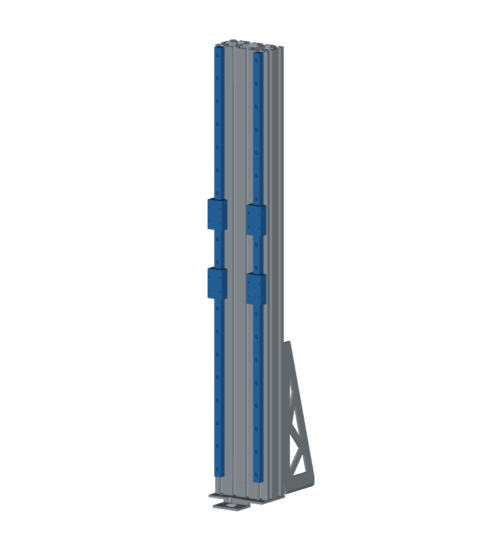
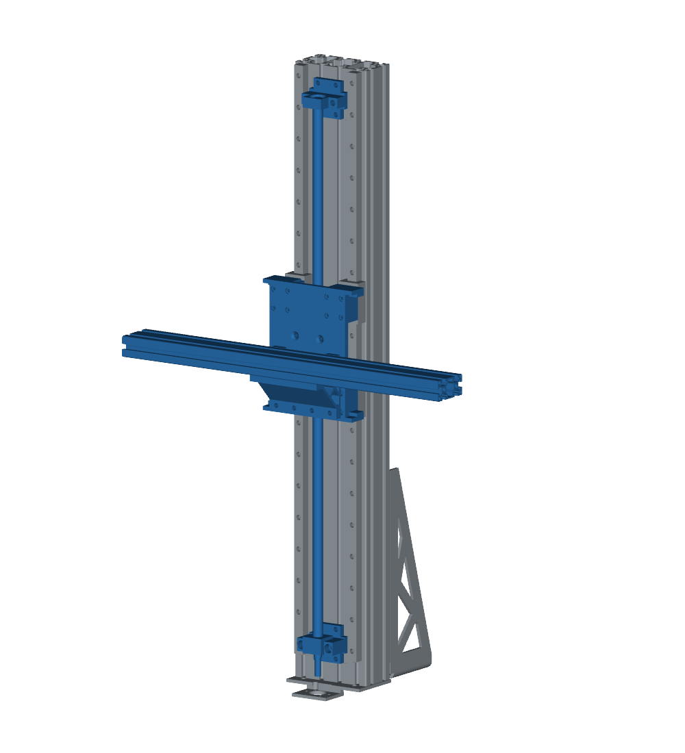
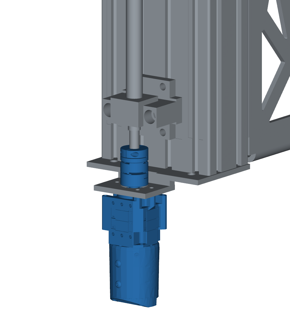
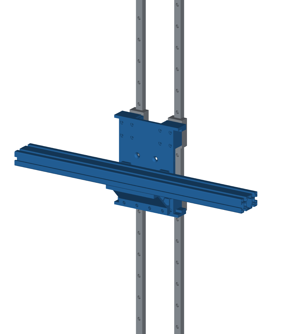
The fixed mast carries two guides. The 20 mm-lead screw moves the carriage and both arms. Blue highlights the parts in each view; most fasteners are hidden. These show the current CAD, not installation trajectories.
Lift travel
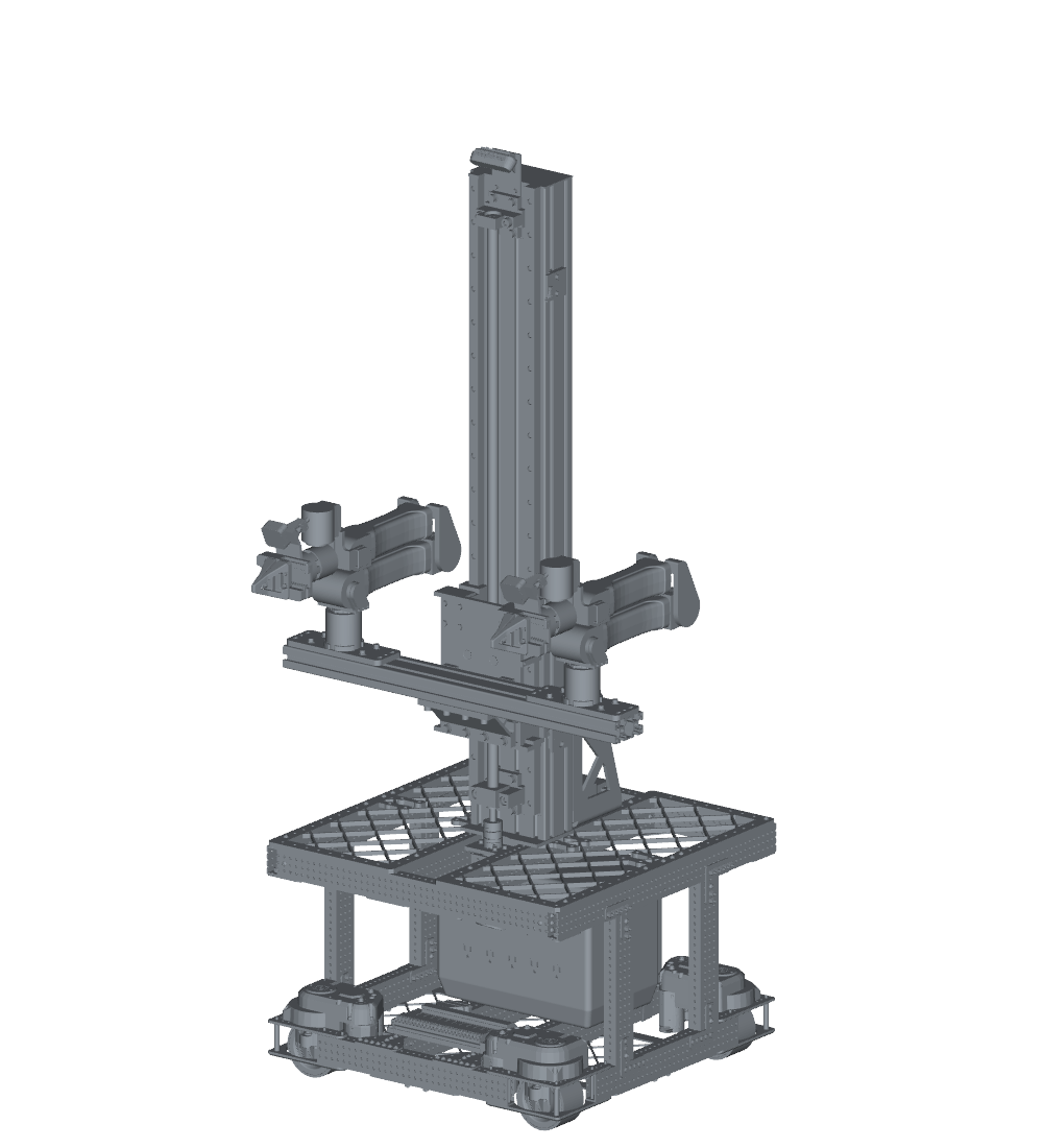
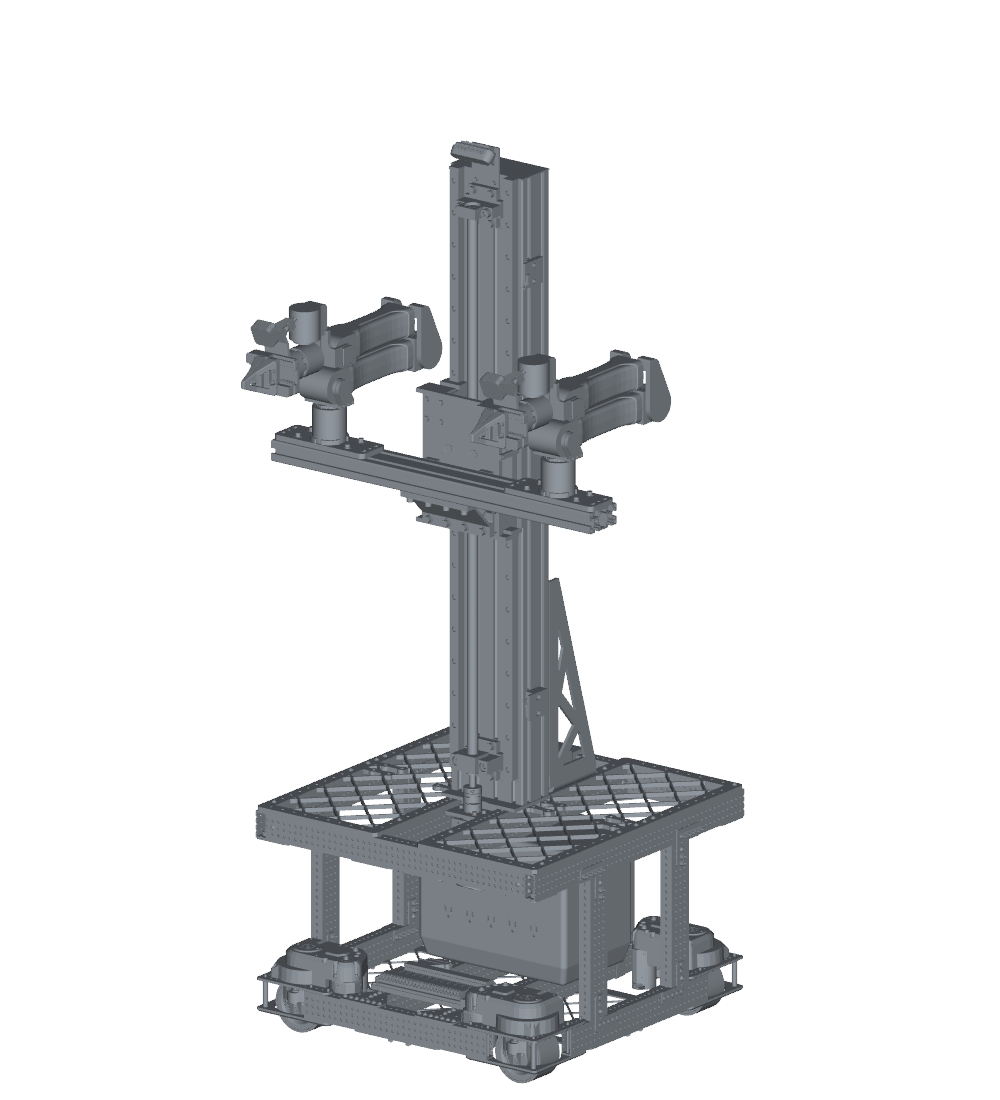
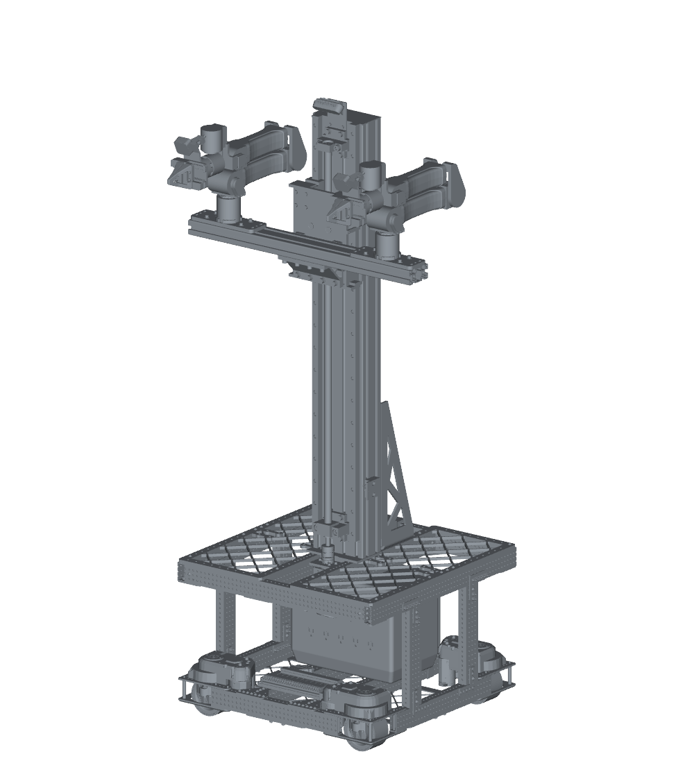
Three positions from the coupled CAD export, spanning 565 mm. Both arms stay in their parked pose. These are geometry views; controller limits and stopping distance still need commissioning.
Access and alignment
Use the final fabrication drawings. Stop mounts, adapter details and some joint torques remain unfinished; see design status.
| Location | Assembly note |
|---|---|
| Mast ends | Insert 19 HNTT8-5 nuts per rail before closing the ends. Each rail uses 19 M5 × 20 screws, without washers under the recessed heads. Reserve four screws and nuts for the switches. |
| Mast/cradle | Fit bottom and rear mounting hardware while the frame fasteners remain accessible. |
| Guides | Follow HIWIN’s alignment procedure on the finished seats. Keep blocks on rails or transfer retainers and running surfaces clean; never tighten a binding carriage into alignment. |
| Ballnut | Keep it on the screw. Fit its four M5 × 16 flange screws and allocated washers before attaching the carriage. |
| Bearing supports | Assemble on the bench using the MISUMI procedure. Keep the screw parallel to the rails; the floating support must not push it sideways. |
| Carriage | Eight upper M5 × 50 socket-head screws and eight lower M5 × 45 button-head screws, with allocated washers. These lengths depend on the corrected seats. |
| REV stack | Fit the input coupler, motor screws and output-shaft retention screw before closing the stack. Use the final shaft drawing for coupling engagement and specified clamp torque. |
| Arm beam | Fit support hardware while the carriage rear is accessible. The arms use eight M6 × 22 screws, existing washers and eight HNTT8-6 nuts. |
| Unloaded travel | Support the carriage independently. With the drive disconnected, check for binding before adding the arms. |
Limits and stops
The two mast-side switch brackets use four M5 × 20 screws, four washers and four HNTT8-5 nuts in total. These are the remaining four fasteners from the 42-piece rail/switch allocation, not an additional purchase. The moving cam uses two M3 × 16 screws and two washers into the carriage. Adjust switch positions in their slots using actual electrical actuation. The CAD now includes lever and roller pivots. Its 12.92-degree lever range represents 3 mm of nominal roller travel from the supplier drawing; it is not an electrical trip setting.
ACE supplied ML3325M and 250-0294 mounting-foot models. The current review uses four custom adapters and an integral carriage striker. The adapter screw rows now match the measured mast slots. Nominal nut seating and screw engagement have been checked. The candidate also clears the parked arms and base at three lift heights. Loaded-joint capacity and finished countersink tolerances remain unfinished; ACE still needs to confirm foot separation and stopping force. Do not manufacture the earlier S33 layout or the current review candidates.
For the adapter candidate, tighten its mast screws before fitting the absorber kit; the feet block two driver paths. This assembly sequence remains provisional.
We sent ACE the rotational-energy calculation and requested sizing over the actual absorber stroke. Peak force and adjustment remain pending. Final switch trip positions depend on the completed stop arrangement. The switch brackets are not mechanical stops.
Mast camera
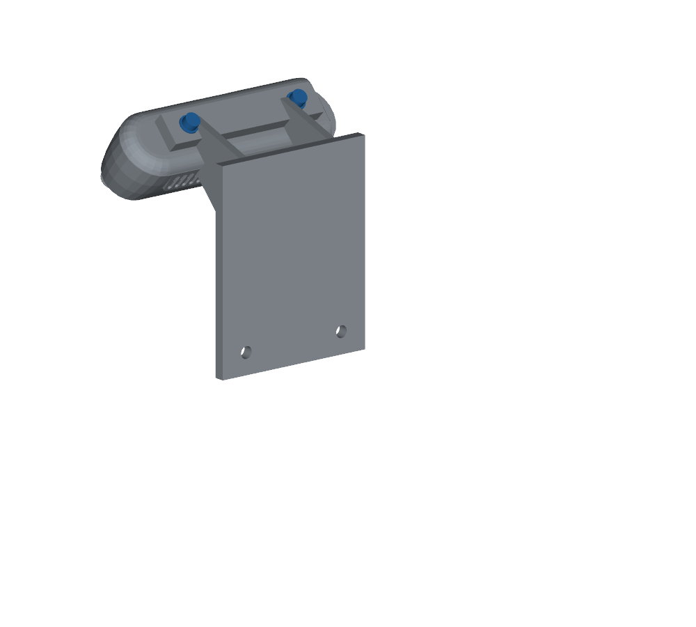
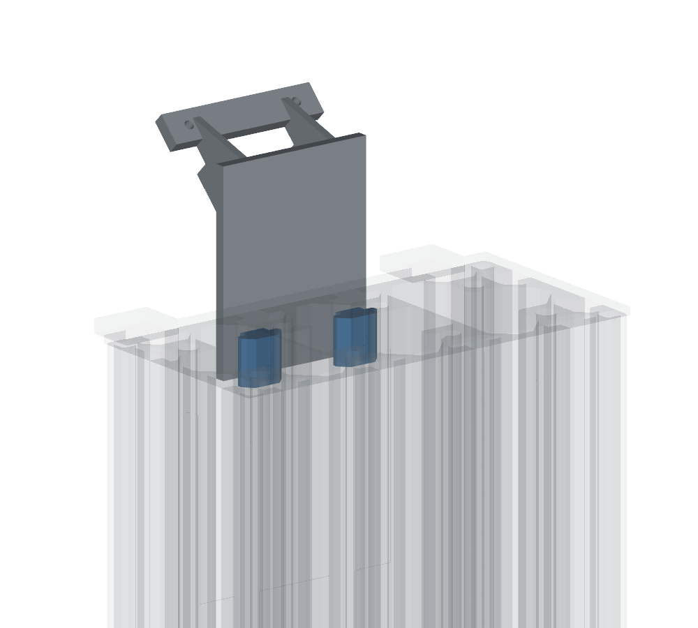
| Interface | Hardware | Check |
|---|---|---|
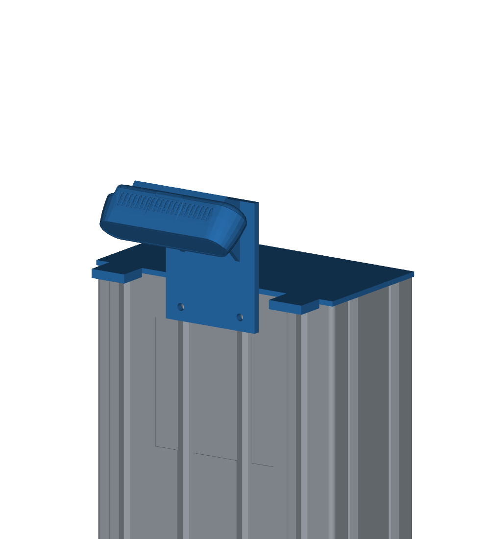
| Camera to printed bracket | Two M3 × 8 socket-head screws; two existing 0.5 mm M3 washers | A 5 mm bracket leaves 2.5 mm insertion. Measure the print; maximum camera insertion is 3 mm. Recommended torque: 0.4 Nm. |
| Bracket to mast | Two M4 × 16 screws; two 0.8 mm washers; two HNTT8-4 nuts | Nominal screw engagement is 8.7 mm in each 9 mm nut body. CAD excludes thread chamfers and manufacturing tolerances. |
| USB cable | Strain relief at the mast | Keep cable loads off the camera connector. |
Hardware is allocated in the mast-camera BOM section; both nuts are constrained in CAD and clear the modeled lift parts. Camera insertion and torque limits come from page 139 of the D400 datasheet . These views show installed geometry, with the mast transparent to expose the nuts.
Before powered motion
Check free travel, bearing alignment, fastener engagement and tool access. Then verify limit input states, controller current limits and direction with an unloaded, restrained setup. Brake behavior, stopping distance and loaded motion require physical tests. The CAD travel range is not a controller setting.
Arm motion
The parked arm pose clears the checked lift parts and top panels at the lower, middle and upper carriage positions. The check includes wrist cameras and brackets.
Do not test an arm by sweeping each joint through its full range while the other joints stay parked. The CAD mesh check found these contacts on both arms:
| Pose with other joints parked | Contact |
|---|---|
| Joint 4 at its negative limit | Gripper/fingers contact the support beam; several arm links contact their own base or other links. |
| Joint 2 at 210 degrees | Arm links contact their own base and other links. |
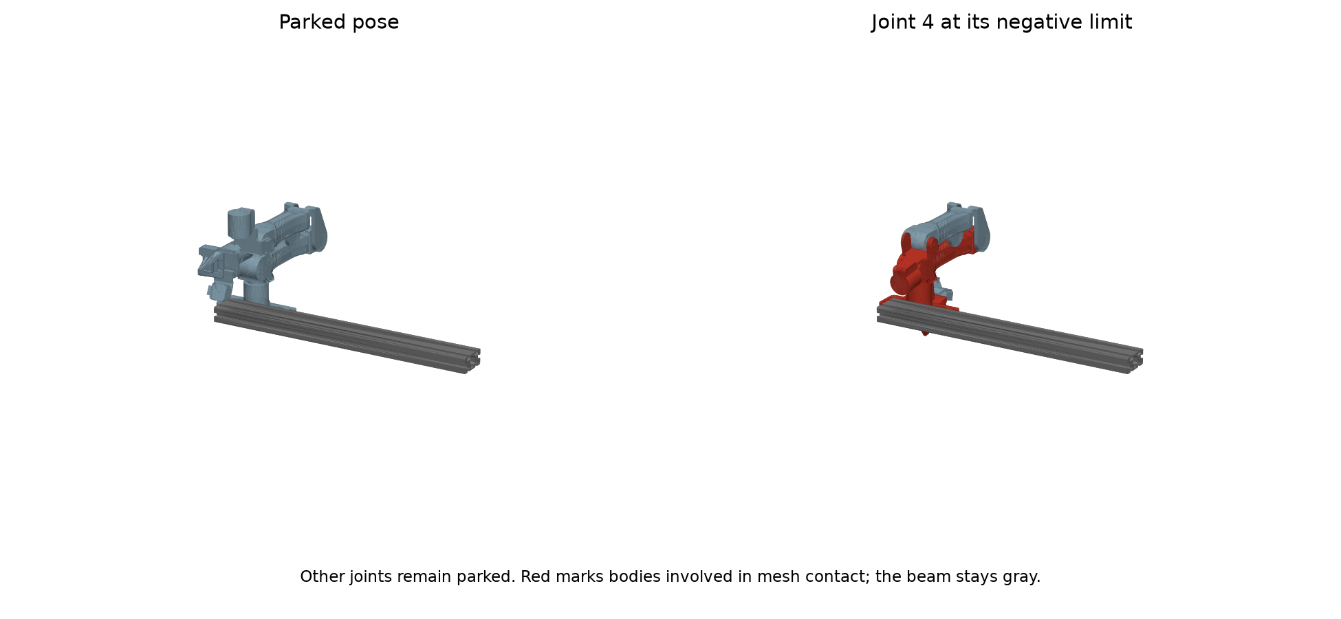
Commissioning needs coordinated, clearance-checked arm poses. The supplier joint limits alone do not prevent these contacts. The check covered 32 joint-endpoint poses and the parked pose at three lift heights; it does not cover continuous trajectories, cables or every base component.